Many different protocols are used in hardware communication. It can get confusing to understand the logic behind these protocols, their different purposes, advantages and drawback. I wanted to know a bit more around how they work really.
First, we can distinguish two kind of protocols:
Parallel protocols:
They require a set of wires to transmit data + one wire to transmit clock sync pulses.The number of wires depends of the speed of the parallel protocol.
An 8 bits speed would require 9 wires, 8 for each bit + 1 for the clock pulses.
Same for 32 bits, 64 bits...
This is called a data Bus, as it moves data (bits) by a number of bits equal to the number of (data) wires.
This articles explains very clearly the relation between Bus speed and number of wires as well as speed of the clock.
Some famous parallel protocols: FSB (front side bus), PCI, AGP ...
Serial protocols:
Serial protocols stream data one bit after the other.
Some famous serial protocols include: USB (univesal serial bus), SPI, I2C, Ethernet...
Serial protocols can be Synchronous or Asynchronous
- Synchronous serial protocols
This kind of serial protocols transmit data one bit after the other, but use a Clock signal wire to sync data from transmission to reception. The use of a sync signal reduces errors or congestion of data.
- Asynchronous serial protocols
This kind of protocol transmit data with only one line of data, without using any clock signal. Error and congestion control needs to be treated by software.
By extension, when people simply speak of "the serial protocol" they mean this basic async protocol.
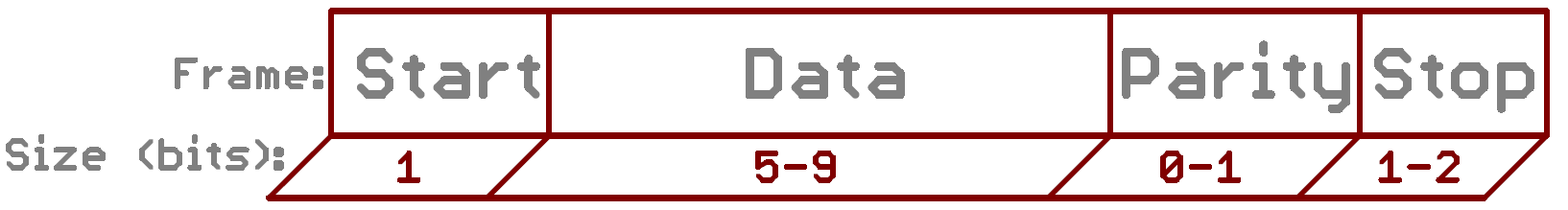
source sparkfun.com
Start, parity and stop bits are there to take care of error control (as there is no sync).
To be able to transmit and receive data correctly, the two end of the connection should "agree" on different parameters on the protocol:
- the data length? how many bits will be transferred?
- the order from which bits will be transferred?
- Big endian (HSB): which means transmit the "most significant bit" first
- Low endian (LSB): transmit the "low significance bit" first
Exemple: Letter "O" => 79 in decimal => "0b01001111" in binary
Sent in LSB => "11110010"
- which will be the sync bits (start and stop)
- will we use a parity bit ?
- the speed at which the bits will be sent (baud rate)
The physical layer:
The serial bus consists of 3 wires: one Rx (receiving data) one Tx (transmitting) and one GND (to share the same ground reference)
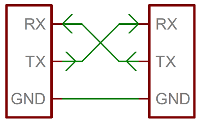

Of course, we must connect the Tx side of one device to the Rx of the other. Bits are sent from one device and received by the other. (the Other wire works the opposite).
Some devices (like LCD sceen works with 2 wires only, as the LCD only receives data and doesn't transmit any thing in return.)
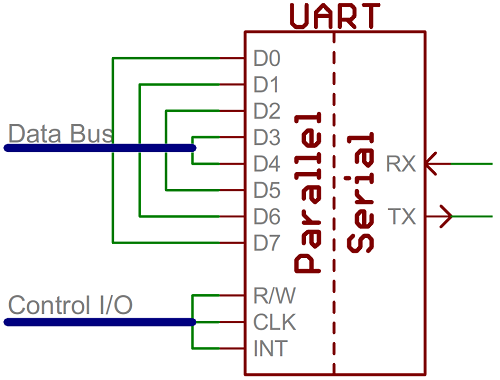
What is UART?
UART (univesal async receiver transmitter) is a protcol, frequently implemented by a dedicated chip that converts data from a serial port / protocol to a parallel protocol (and the other way around).
UART can be done by a dedicated IC or directly by programming the microcontroller.
For exemple, on the arduino UNO, we have only one UART port, on the Leonardo 2...
We can implement virtual UART ports by treating the serial / parallel coding - decoding at the micro-controller level, using for exemple "SoftwareSerial" Arduino Library.
This is called "Bit bangging".
Another point: Serial protocol works only for two devices communicating together. Working with more than two devices will cause communication problems.
What is FTDI ?
FTDI is the name of a company making a chip used to converting RS-232 or TTL serial transmissions to USB signals.
On an Arduino connected to your computer via a USB cable, data communication from your computer and the Arduino is using the USB protocol, which needs to be conveted into the traditional "Serial protocol" (rs-232 or ttl) to be interpreted by the Arduino board. This is the role of the FTDI chip.
Once data is decoded in Serial, it is in turn transcoded into a 8 bits (or more) parallel bus to communicate with the micro-controller. This is done through the UART chip, currently embedded inside most micro-controllers. (inside the ATMEGA chip which is the core of the Arduino board).
Useful resource: a very good article on sparkfun.com
Useful resource: a very good article on sparkfun.com
Commentaires
Enregistrer un commentaire
Tell me what you think