Yesterday, I was looking for a free way to get a voltage regulator to enhance a home irrigation project.
I have re-used an old laptop Switch Mode Power Supply that provides 12v at a max of 3 amps. And I need to get a good efficiency buck converter to reduce current to something close to 5v for the arduino board to use safely.
Even though the arduino boards is said to accept input voltage of up to 20 volts, the regulator is a simple linear one that - to my own experience - will burn if provided with 12 volts during a small time.
I though there should be anything close to a mini SMPS inside these small wall chargers... but there was nothing close to it inside... in fact it is a much more cheaper and simple design...


As you can check by yourself in this video, we can see how poorly and "hand made" the design of these things is really, and for your own safety and that of your device, it is really worth it getting an official one. (I already burnt the brand new Ipod of my wife some years ago).
And this was enough to give me an opportunity to understand better understand two components in a specific use:
1) Transformers used as an isolation or shock protective device
=> First I have heard before that transformers, aside from being able to reduce or increase the voltage of an alternative current, was able to isolate one part of a circuit from the other.
Here is a short explanation of how it really works:
Basically, one part of the AC circuit is connected to ground. (often connected to home 110 or 220v outlet), if you touch one of the two wires, you will be electrocuted as your feet touch the ground with is the same potential as the ground wire. When we "separate" two circuits through a transformer, there is no more physical connection between the two circuits and the second one doesn't share the same "ground" connection, which may protect you as the voltage of this part of the circuit is not any more referenced between the earth ground.
http://www.learnabout-electronics.org/ac_theory/transformers03.php#isolation
2) Zener diodes, used as a cheap small current voltage regulator
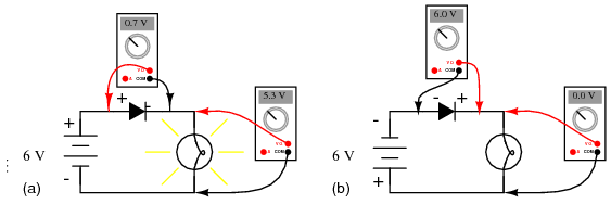
Note on standard Diodes: standard diodes let current pass only in one way, with a voltage drop of 0,6v (to take into consideration if we deal with small voltages)
Zener diodes are a kind of diode that have a specific behavior: they will allow current to flow on the other side only after the "zener breakdown voltage", they need also a small current to pass on them to work. We need to add a resistor in serie to a zener diode to allow for a small current to pass.
The Resistor needs to be selected according to the current needed to operate correctly.
A Zener specified at 5v at 50ma, will only drop 1v at 10uA.
To calculate the series resistor value needed, you need to estimate how much current the Load will draw. If it is 1ma and the Zener needs 10ma for 5v:
12v - 5v = 7v
R = 7v / 0,11A = 640 Ω needed at least

When we supply DC voltage from Vin to Gnd, Vout gets reduced to the Voltage specified by the Zener Diode, as it will allow only this value to pass to ground.
It is a great way to provide a reference voltage as it will not depend to the resistance of the Load and the input voltage as in a tradicional voltage divider.
The zener diode will "clamp" the same voltage *constant* across it's terminals (assuming there's enough in the supply voltage). The voltage divider's voltage will vary *proportionally* to the supply voltage.
Interesting point:
Because a standard diode has a 0.7 v voltage drop on its normal current-passing way, we can use it as tiny voltage regulator adding a few diodes in serie, if we hadn't a zener available on the proper voltage.

Very good resource on using Zener diodes to regulate voltage and how to calculate Resitor value according to load: (IE arduino using up to 30mA)
http://www.instructables.com/id/Zener-Diode-Shunt-Regulator/
I have re-used an old laptop Switch Mode Power Supply that provides 12v at a max of 3 amps. And I need to get a good efficiency buck converter to reduce current to something close to 5v for the arduino board to use safely.
Even though the arduino boards is said to accept input voltage of up to 20 volts, the regulator is a simple linear one that - to my own experience - will burn if provided with 12 volts during a small time.
I though there should be anything close to a mini SMPS inside these small wall chargers... but there was nothing close to it inside... in fact it is a much more cheaper and simple design...


As you can check by yourself in this video, we can see how poorly and "hand made" the design of these things is really, and for your own safety and that of your device, it is really worth it getting an official one. (I already burnt the brand new Ipod of my wife some years ago).
And this was enough to give me an opportunity to understand better understand two components in a specific use:
1) Transformers used as an isolation or shock protective device
=> First I have heard before that transformers, aside from being able to reduce or increase the voltage of an alternative current, was able to isolate one part of a circuit from the other.
Here is a short explanation of how it really works:
Basically, one part of the AC circuit is connected to ground. (often connected to home 110 or 220v outlet), if you touch one of the two wires, you will be electrocuted as your feet touch the ground with is the same potential as the ground wire. When we "separate" two circuits through a transformer, there is no more physical connection between the two circuits and the second one doesn't share the same "ground" connection, which may protect you as the voltage of this part of the circuit is not any more referenced between the earth ground.
http://www.learnabout-electronics.org/ac_theory/transformers03.php#isolation
2) Zener diodes, used as a cheap small current voltage regulator
Note on standard Diodes: standard diodes let current pass only in one way, with a voltage drop of 0,6v (to take into consideration if we deal with small voltages)
Zener diodes are a kind of diode that have a specific behavior: they will allow current to flow on the other side only after the "zener breakdown voltage", they need also a small current to pass on them to work. We need to add a resistor in serie to a zener diode to allow for a small current to pass.
The Resistor needs to be selected according to the current needed to operate correctly.
A Zener specified at 5v at 50ma, will only drop 1v at 10uA.
To calculate the series resistor value needed, you need to estimate how much current the Load will draw. If it is 1ma and the Zener needs 10ma for 5v:
12v - 5v = 7v
R = 7v / 0,11A = 640 Ω needed at least
When we supply DC voltage from Vin to Gnd, Vout gets reduced to the Voltage specified by the Zener Diode, as it will allow only this value to pass to ground.
It is a great way to provide a reference voltage as it will not depend to the resistance of the Load and the input voltage as in a tradicional voltage divider.
The zener diode will "clamp" the same voltage *constant* across it's terminals (assuming there's enough in the supply voltage). The voltage divider's voltage will vary *proportionally* to the supply voltage.
Interesting point:
Because a standard diode has a 0.7 v voltage drop on its normal current-passing way, we can use it as tiny voltage regulator adding a few diodes in serie, if we hadn't a zener available on the proper voltage.
Very good resource on using Zener diodes to regulate voltage and how to calculate Resitor value according to load: (IE arduino using up to 30mA)
http://www.instructables.com/id/Zener-Diode-Shunt-Regulator/
Commentaires
Enregistrer un commentaire
Tell me what you think